- Your cart is empty
- Continue Shopping


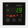
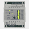
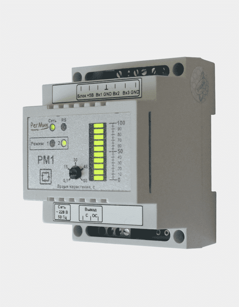
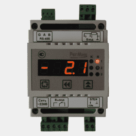
Power regulator PM1

2760 ₴
The device controls and regulates the power in the active load on one channel. Sensors with a unified current or voltage output signal can be used as a driver.
Purpose:
Power regulators are designed for:
- power control in active load, power triacs connected to the device;
- use as a power setting device of a manually controlled heater, as well as for automatic maintenance of the object temperature in conjunction with thermostats (for example, RD1, RP1, etc.).
General functions and operating modes:
The power regulator works in automatic mode. When a voltage of 0 ... 10V is applied to the control input, the device proportionally regulates the output power of the active load in the range of 0 ... 100%.
The device provides a smooth output to the set power. This is necessary to avoid sudden overloads of the supply network. When the device is turned on or when the signal level changes abruptly at the control input of the device, the power in the load increases not abruptly, but smoothly. The time for reaching the set power is adjustable from 0.1 to 60 seconds, which is set using the knob on the front panel of the device.
The "inhibit" input signal inhibits the triggering of control pulses. When it is removed, a smooth exit to a given power level will occur. An n – p – n type transistor with an open collector output or contacts of a button, toggle switch, reed switch, relay can be used as a source of the "blocking" signal.
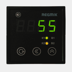
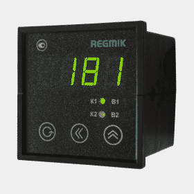
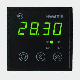
The operating mode is displayed on the front panel of the device and changed by software. The factory performs an initial calibration of the analog inputs with the factory settings.
To regulate the power on the load, the device allows you to generate signals that control the triacs by two methods: phase or by the number of half periods.
The phase method is used to control low-inertia objects that are responsible for changing the voltage across the load, as well as when controlling lighting. With the phase method, the device changes the opening angle of the triac depending on the value of the signal at the control input, thereby changing the power level at the load.
The half-cycle control method is applicable only for inertial loads. The number of half-periods on the load depends on the value of the signal at the control input: at the minimum power level (0%), half-waves of voltage are not received, at the maximum power level (100%), 100 half-waves are supplied to the load, and at 50% power - 50 half-waves of the supply voltage.
Characteristics
Analog input parameters
| Characteristics | AN | AT |
|---|---|---|
| Working hours | 2 | 3 |
| Factory settings | 0 ... 10 V | 4 ... 20 mA |
| Minimum calibration value | 0 in | 0 mA |
| Maximum calibration value | 10 in | 20 mA |
Main technical characteristics of the power regulator
| Description of characteristics | Value |
|---|---|
| Supply voltage (from AC mains), V | 220 (± 15) |
| Mains frequency, Hz | 50 (± 10) |
| Power consumption, W | no more than 3 |
| Instrument control mode | control signal 0 ... 10 V |
| Power triac control method | mode No. 1 - phase mode number 2 - pulse (by number of periods) |
| Device width, mm | 67 |
| Weight, g (no more) | 400 |
Application examples
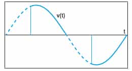
Dimming of light-emitting diode lamps (LED) by the "phase-cut" method
Dimming according to the "phase cut-off" technology, with the help of which a part of the sinusoid of the mains voltage is cut off, and
effective voltage on the lamp. If this cutoff is applied to the origin of a sine wave, the dimming method is called front dimming.
leading edge ”, if clipping is applied to the end of the sine wave, the dimming method is called“ falling edge dimming ”. These two methods are used to
dimming of different types of lamps: “Trailing edge dimming” is more suitable for low voltage lamps (LED or halogen) with
electronic transformers. “Leading edge dimming” is more suitable for low voltage lamps with electromagnetic transformers,
as well as for 220V compact fluorescent lamps and 220V LED lamps. Both methods are suitable for halogen lamps, 230V incandescent lamps, LED lamps with dimmable driver.
Dimming on the trailing edge
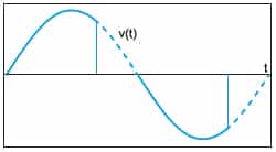
Leading edge dimming
Download
![]() Passport for РМ1 1UV/1OСC-RS485-IPI-D4 V3.6 (Russian)
Passport for РМ1 1UV/1OСC-RS485-IPI-D4 V3.6 (Russian)
![]() Passport for РМ1 1UV/1OСC-RS485-IPI-D4 V3.7 (Ukr.)
Passport for РМ1 1UV/1OСC-RS485-IPI-D4 V3.7 (Ukr.)
You must be logged in to post a review.


Reviews
There are no reviews yet.